Master System RGB Guide
Click on the pictures for a larger view
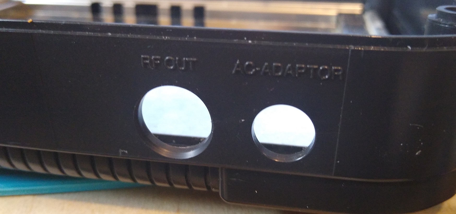
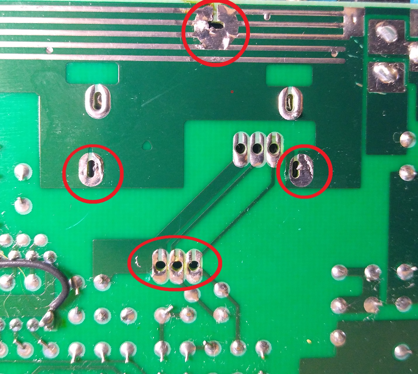
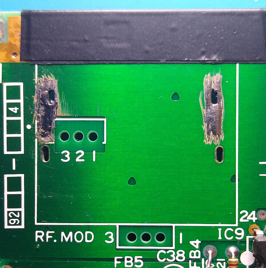
First step is to remove the RF module.
This is held in with 3 soldered mount points and 3 signal points
Once desoldered, you may need to straighten the legs of the mount points before it can lift out
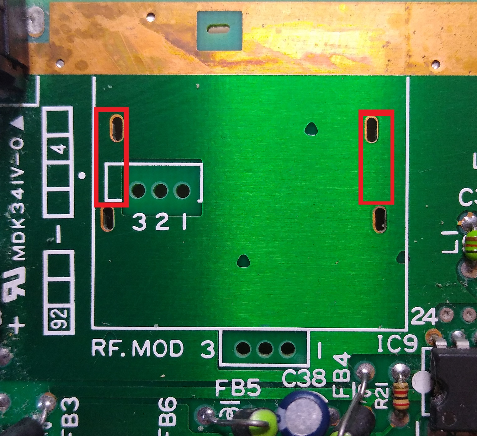
Scrape away some of the solder mask on the top of the board indicated in the image below, this will be used to mount the board in place
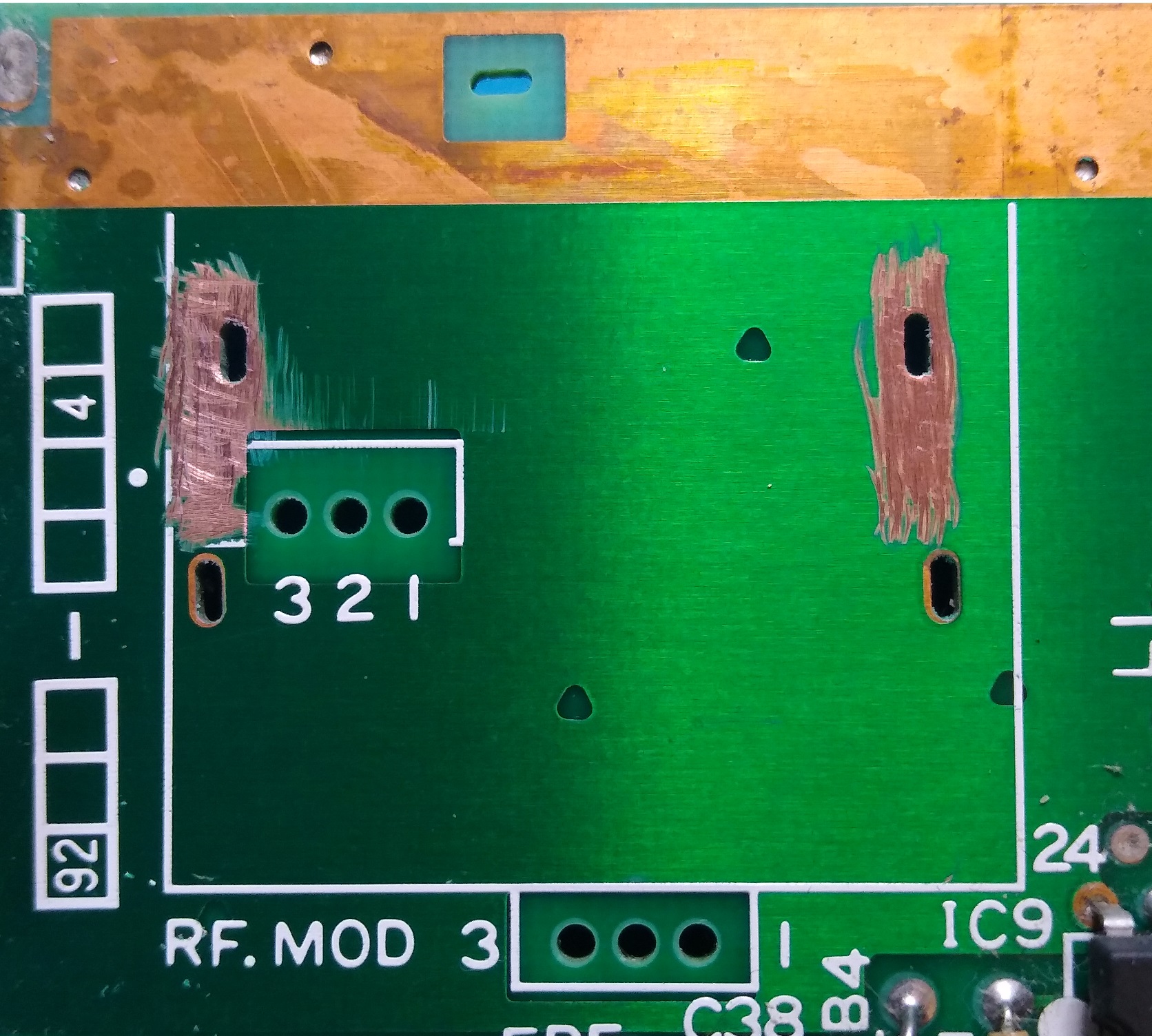
Add a thin layer of solder to the exposed copper areas
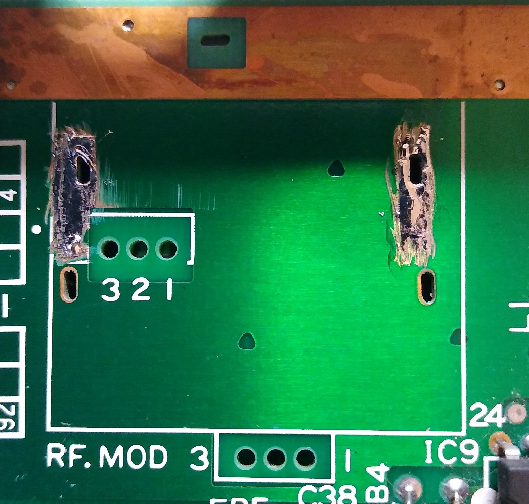
Add electrical tape over the top ground area for insulation
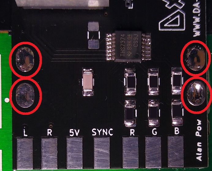
Align the socket with the hole in the case and solder one of the mount points
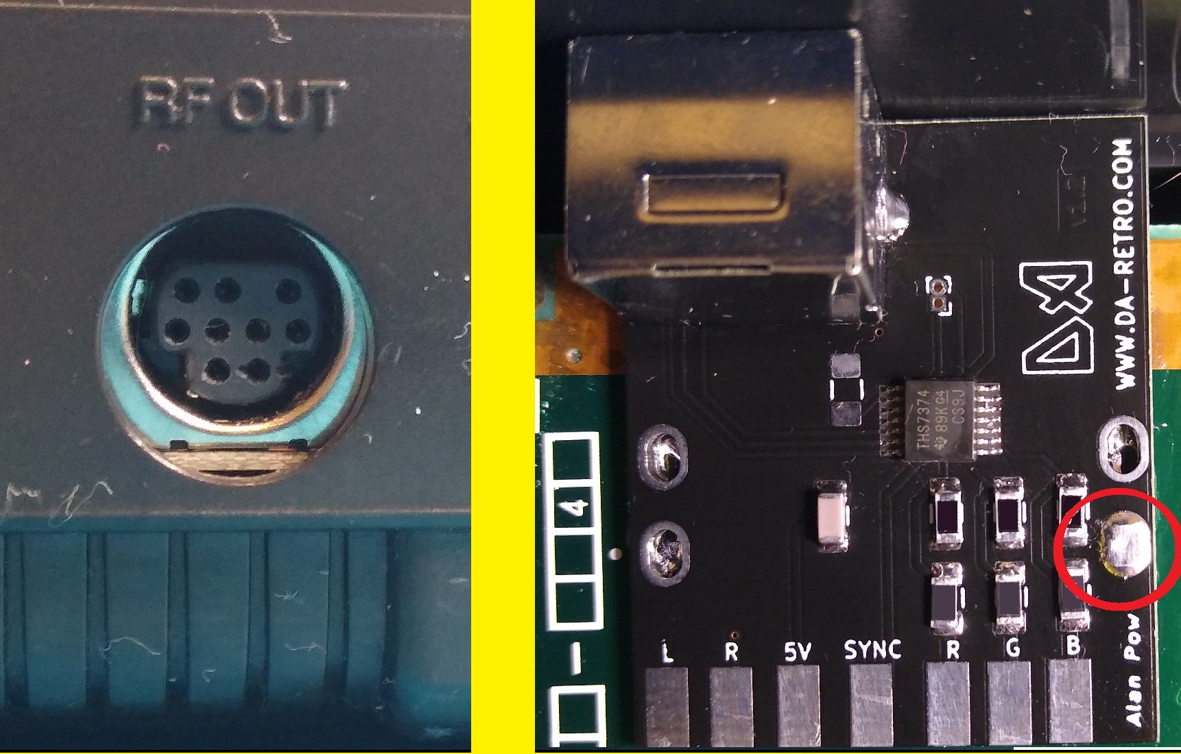
Once you have soldered the first point check the socket is still aligned
If you are happy solder the other 3 points
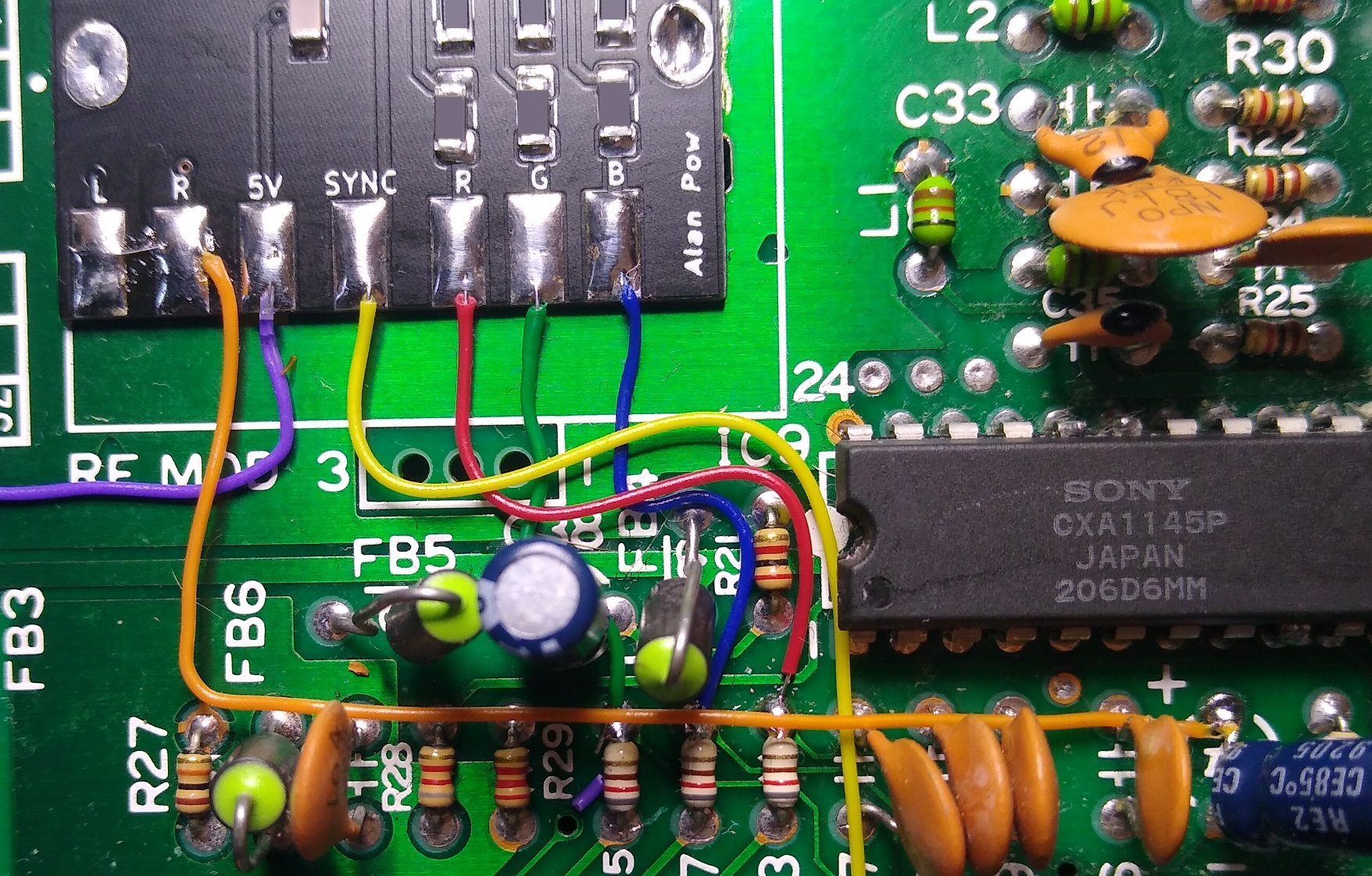
Now to start to connect the pads on the PCB
PCB PAD B to resistor R17
PCB PAD G to resistor R15
PCB PAD R to resistor R13
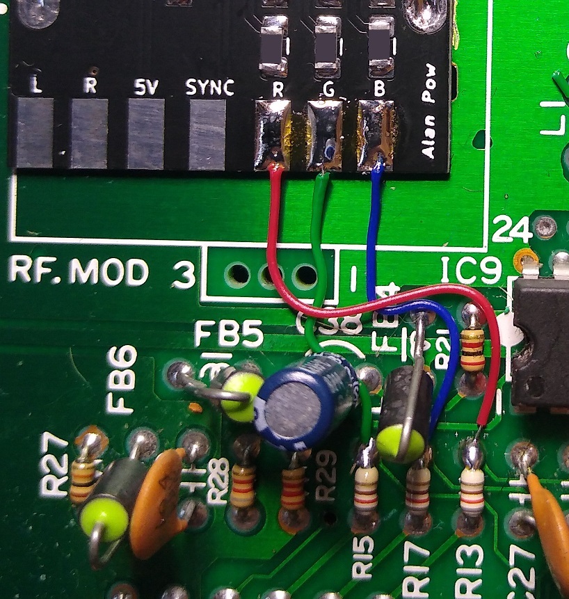
PCB PAD SYNC to Leg 30 of the Sega chip 315-5248
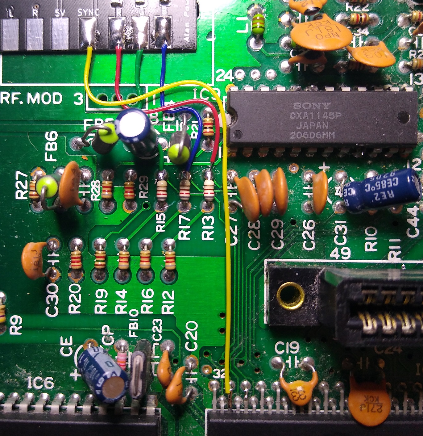
PCB PAD 5v to Capacitor C43
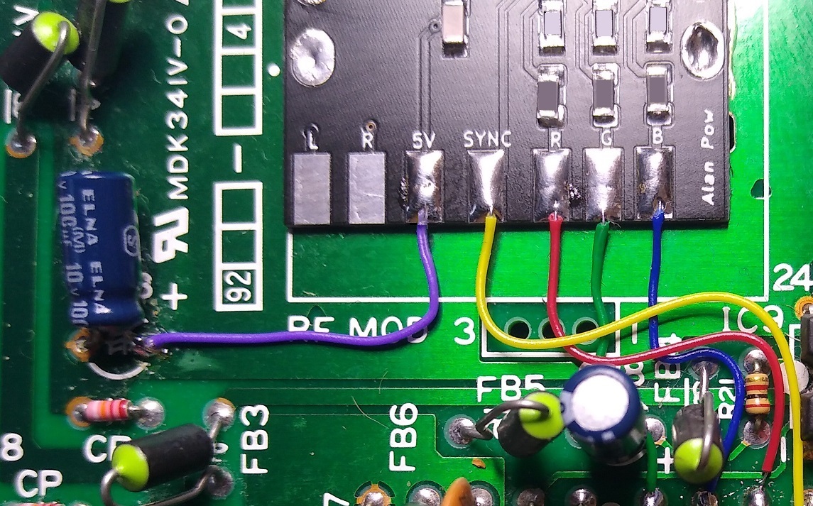
PCB PAD L & R to Capacitor C31
(As the Master System is mono we need to connect to both L & R)
This next step is option but just makes it a bit easier to plug the scart lead in
Drill the RF hole on the case out to 14mm.