
NO RESPONSIBILITY IS TAKEN FOR ANY DAMAGE CAUSED TO YOUR CONSOLE
please continue at your own risk
Sega Saturn Switchless Guide
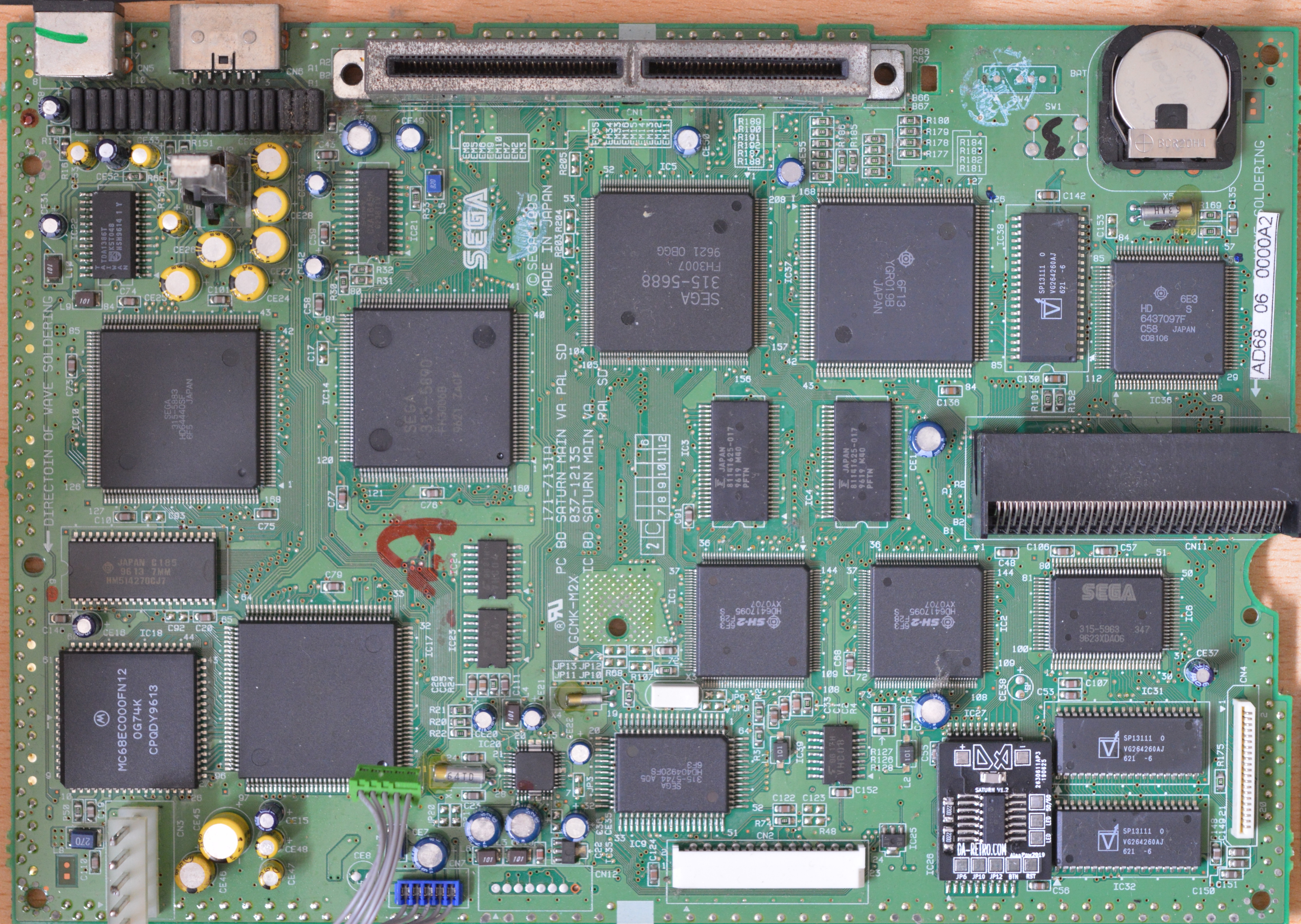
Based on AD65 Serial Number shown below
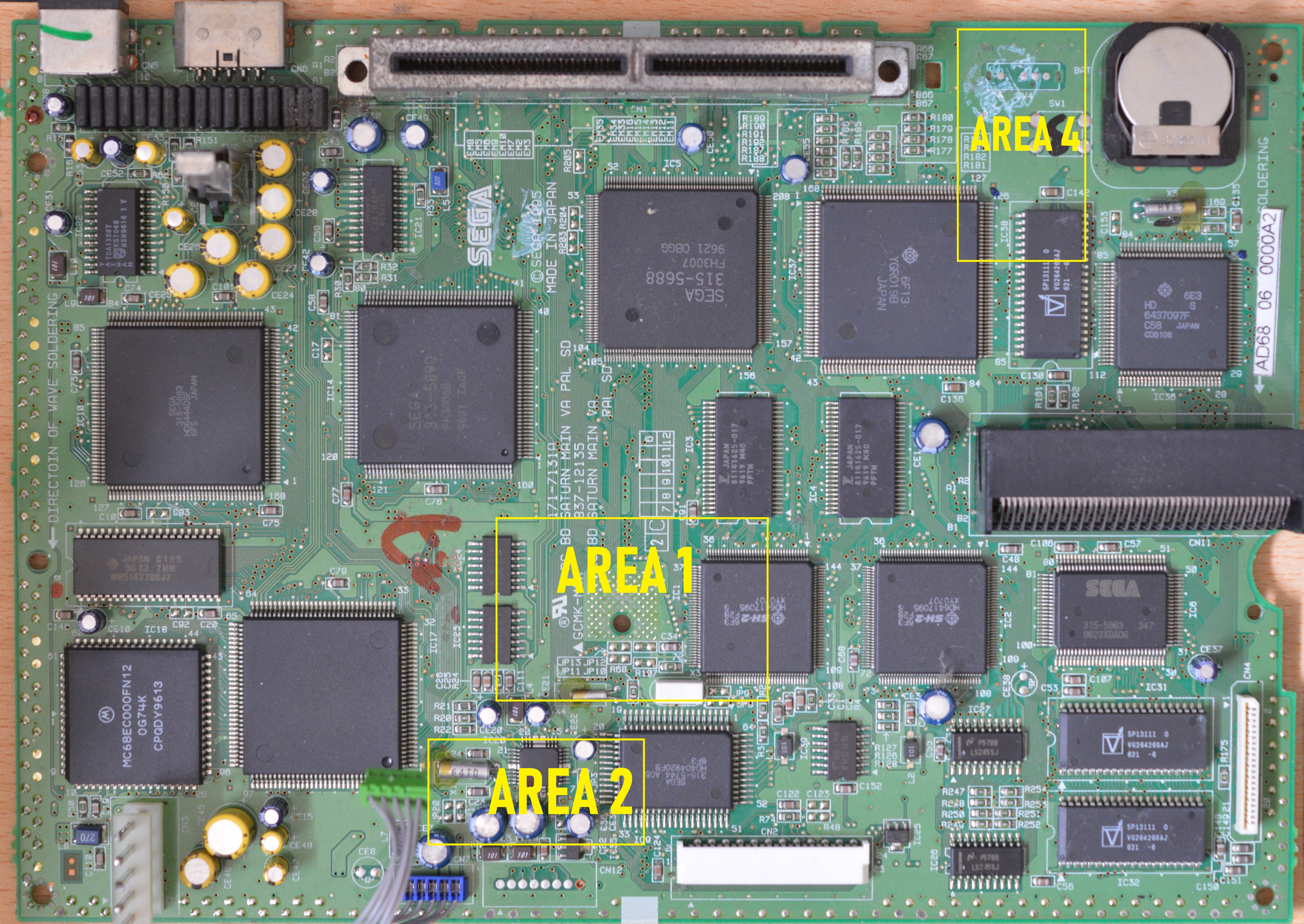
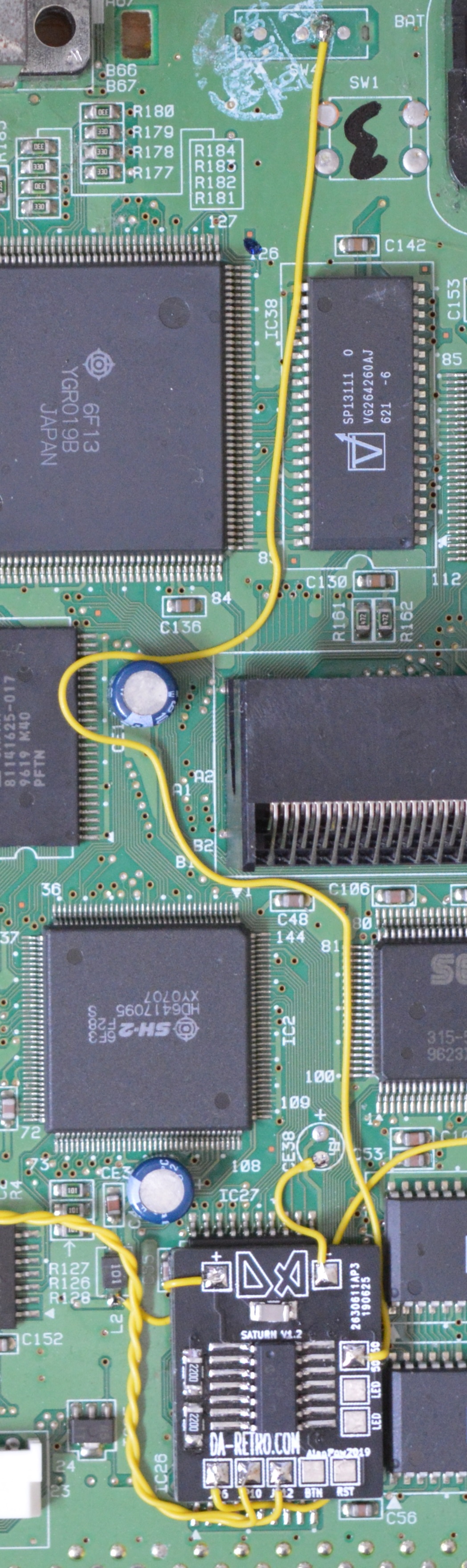
First we need to cut a few tracks starting with JP10 & JP12 located in area 1 above.
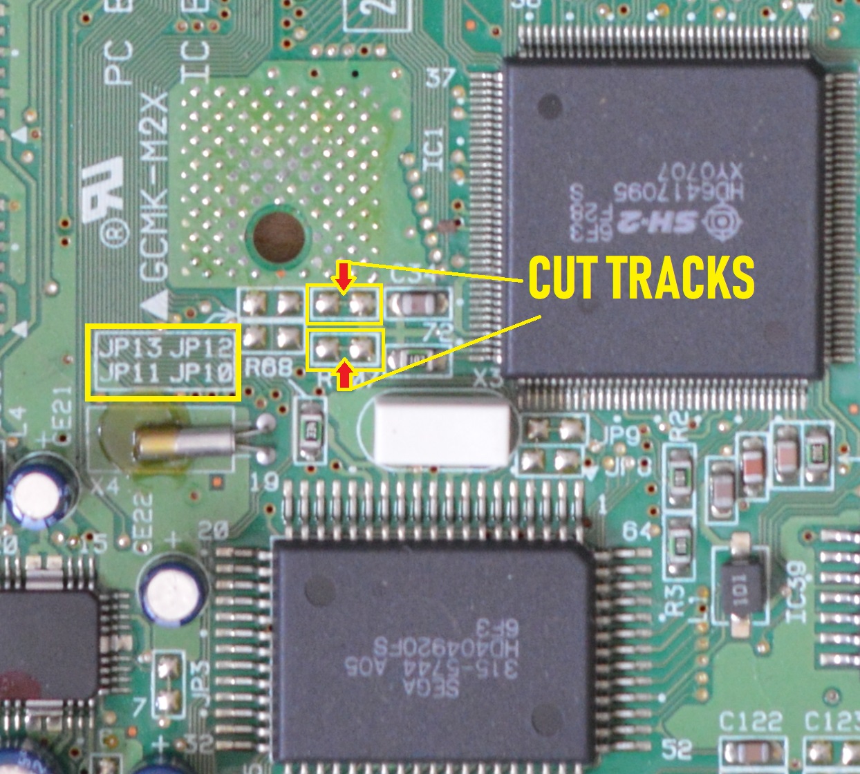
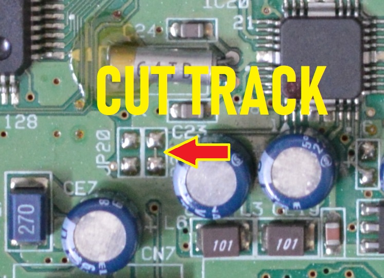
Now head to area 2 can cut JP20
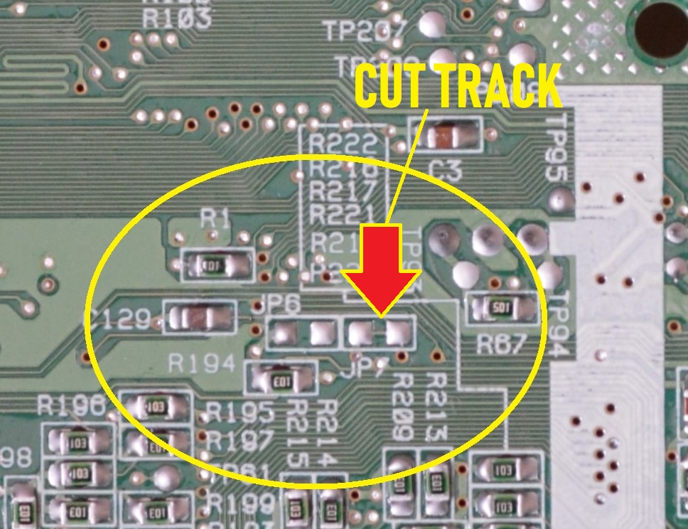
Time to flip over the board to Area 3
be careful not to damage the door close switch when working on the bottom

Cut the link on JP7 shown below
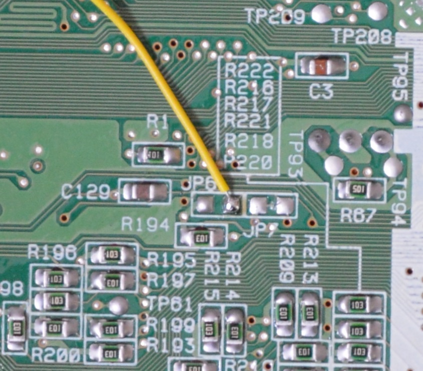
While on the bottom solder a wire onto JP6
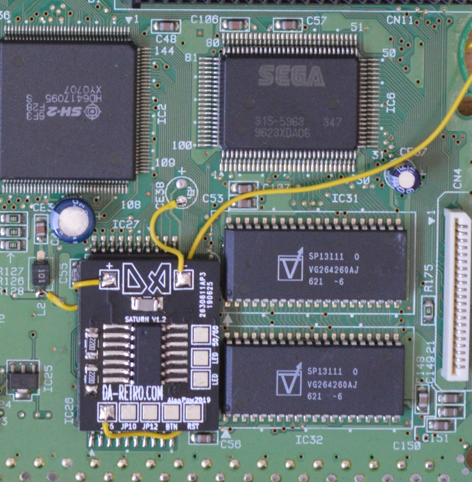
Back on the front, stick the chip in a suitable location
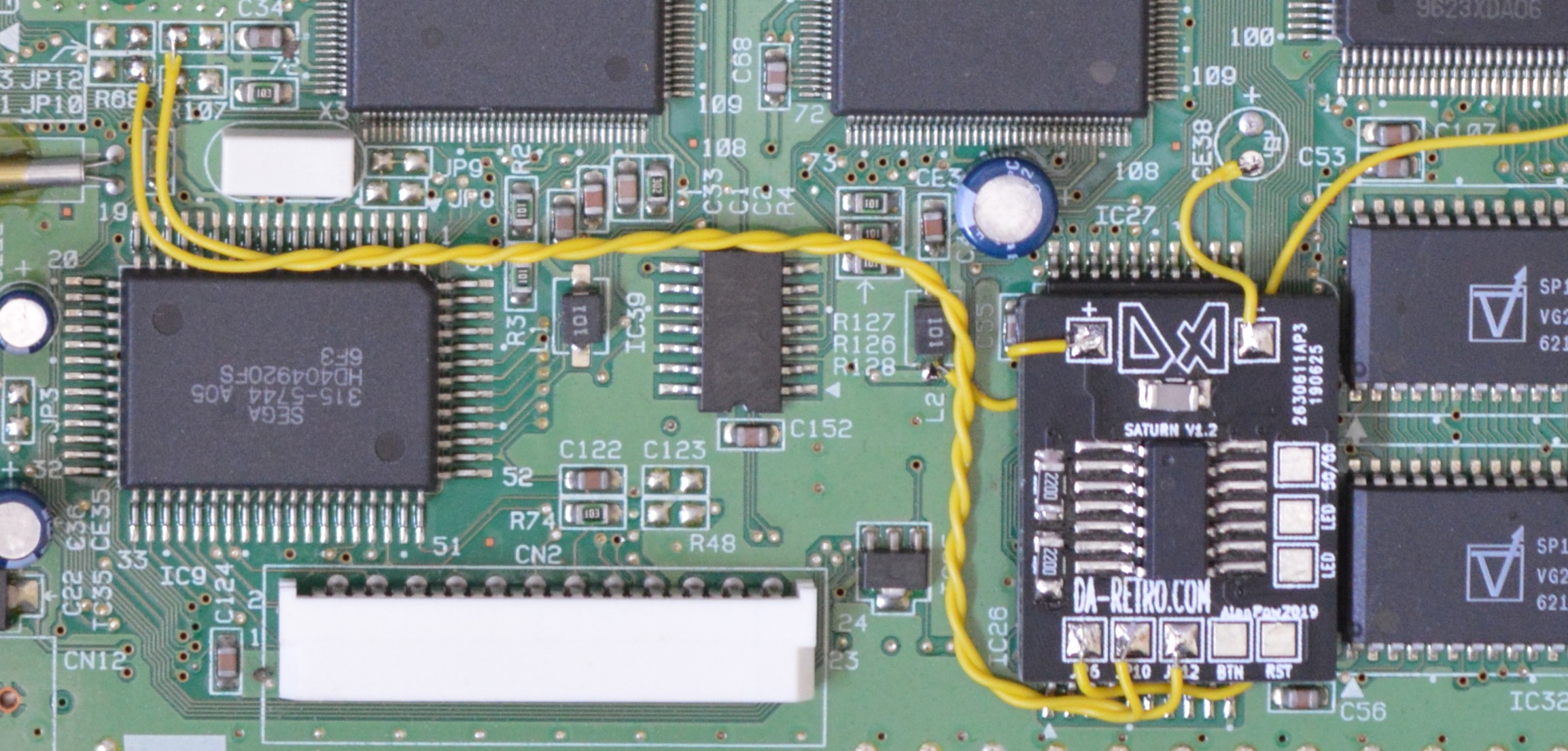
Install the JP6 wire on to the board along with the power wires. 5V can be sourced from L2 and ground from CE38
Now connect wires from JP10 & JP12 in area 1 to the relevant pads on the chip
Next job is in Area4
Solder the wire for the 50/60hz signal
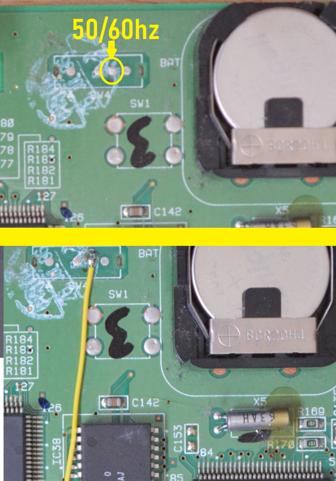
Now we need to link the 50/60 wire from Area 4 to the board
Next we move on to the separate board with the reset button and controller ports
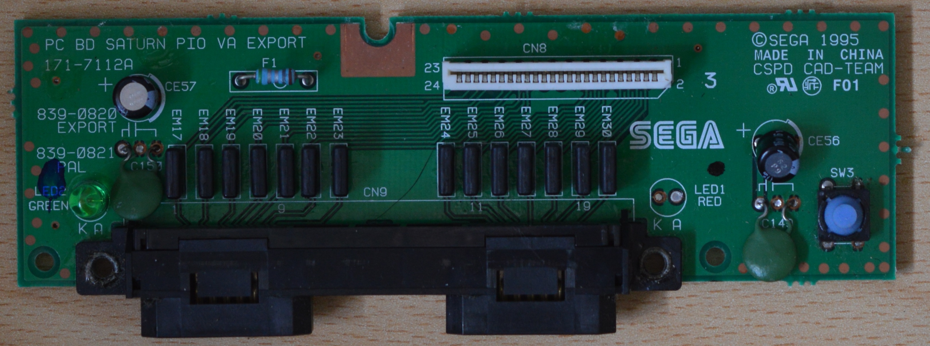
Remove the original LED
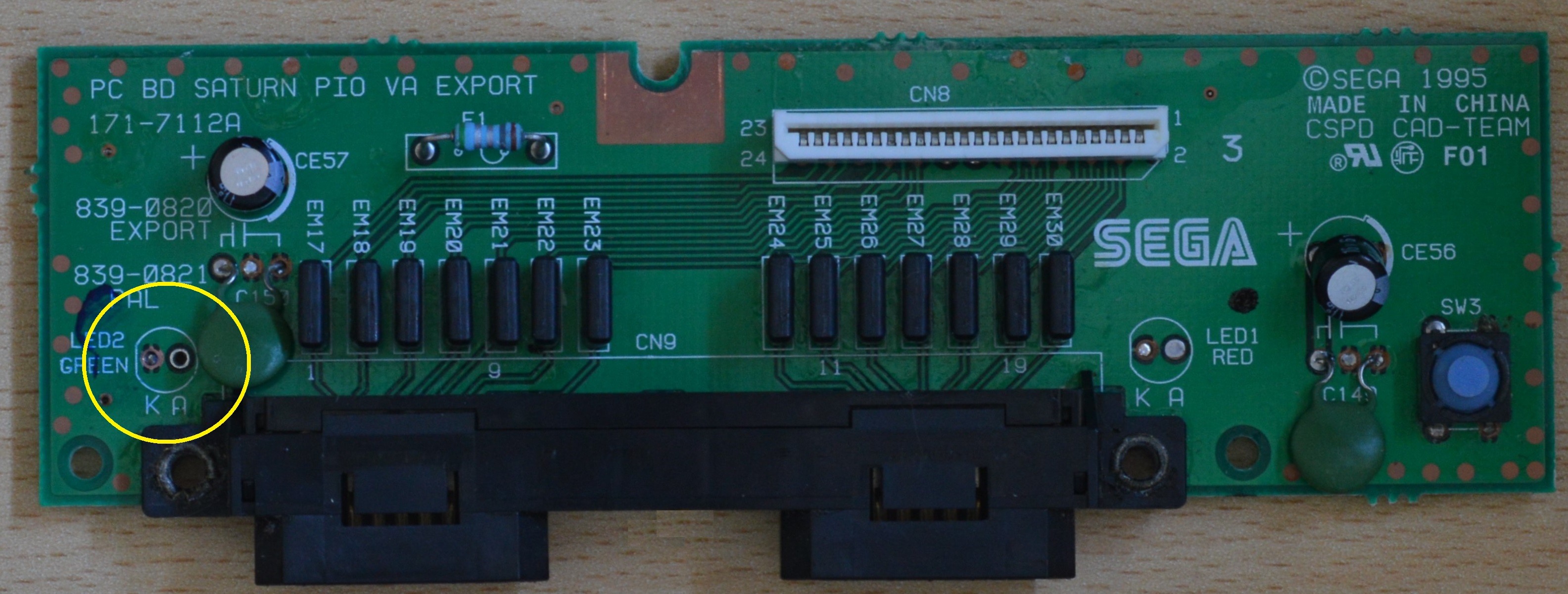
Scrape away a small section on the solder mask so that you can earth the new LED then fit it the LED on to the board
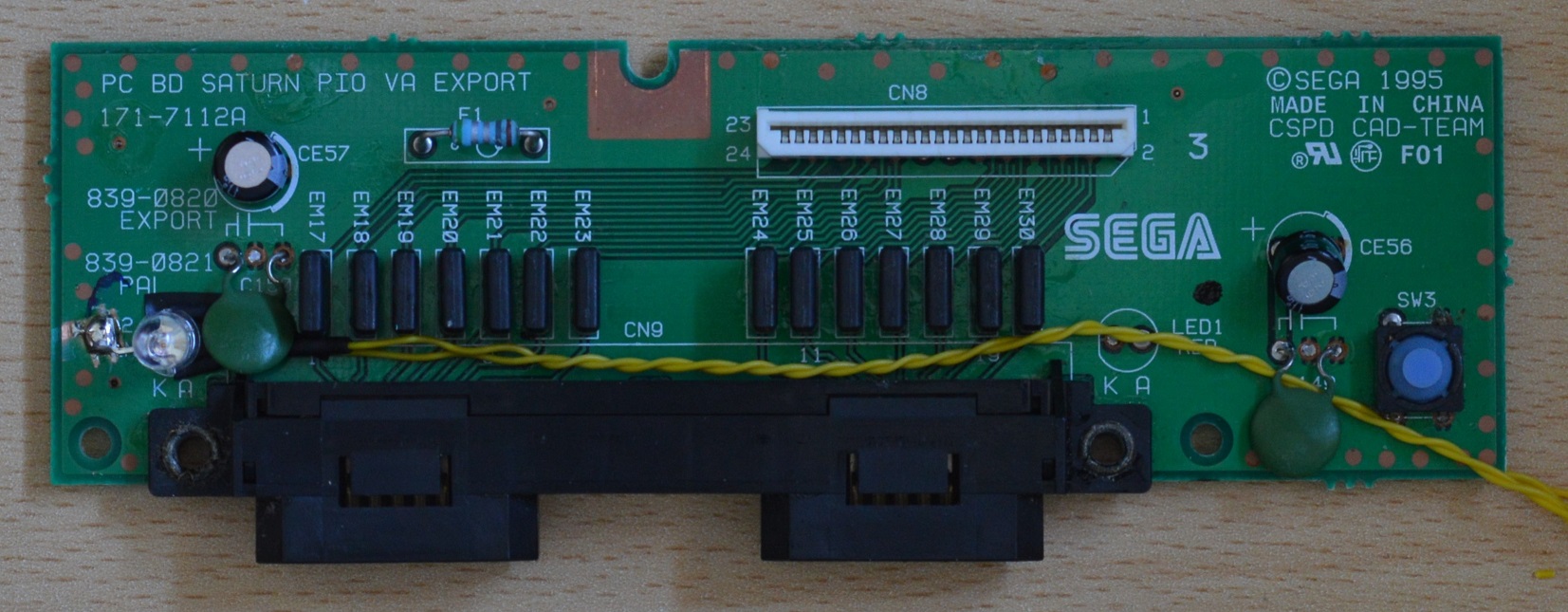
Turn to the bottom of the board and cut the track from the reset button
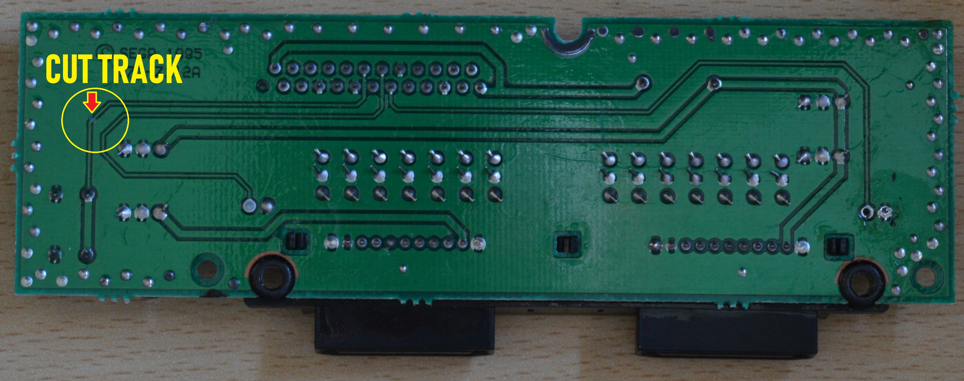
and solder a wire at each end on the track
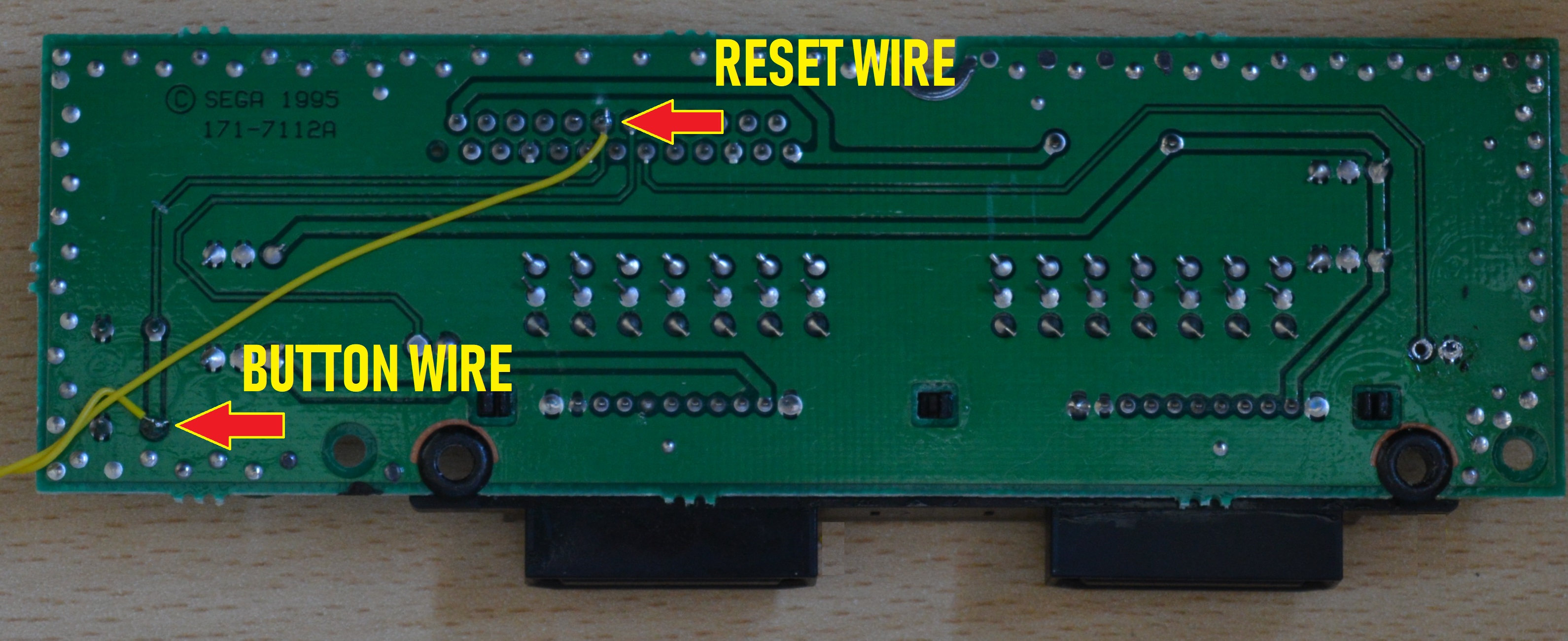
Connect the 4 wires back to the chip, Sitting the boards back in to the case will doing this helps with wire lengths and routing
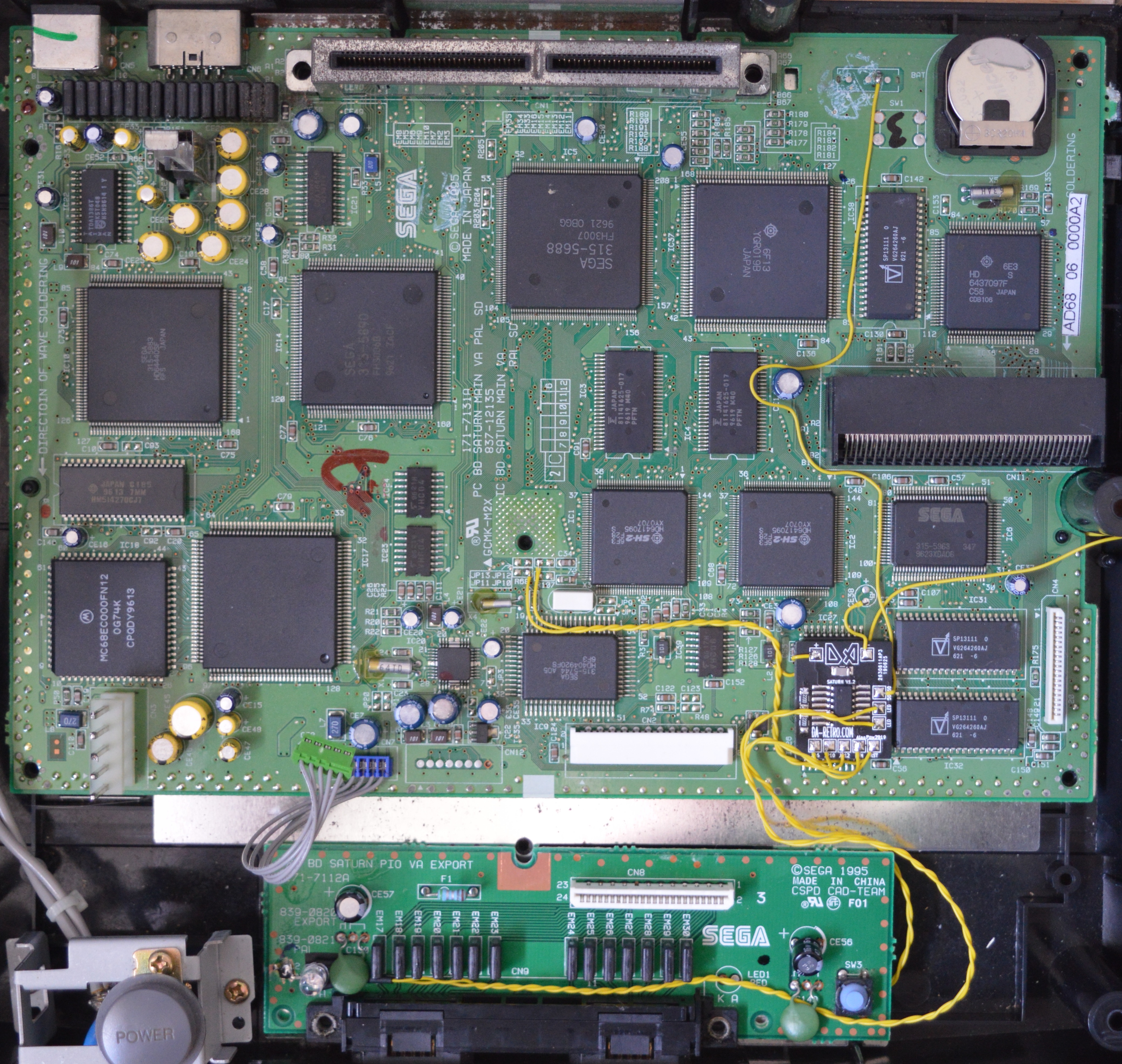
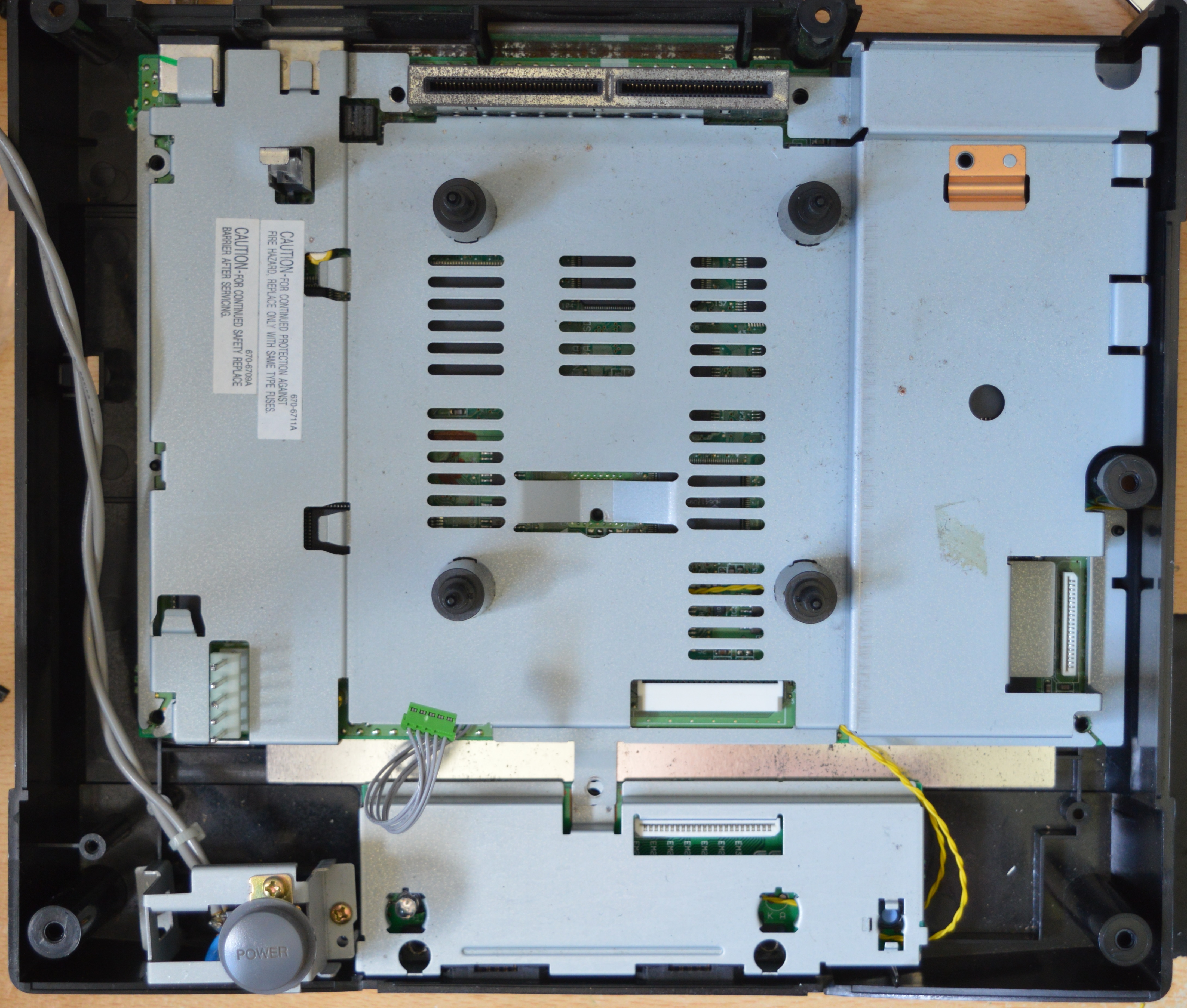
There is a convenient slot in the metal heat shield for the wires to fit
This is the modification complete, please fully assemble the console before testing as the PSU does have exposed high voltage components.
To check the regions are working correctly you can go into the Saturn's settings menu and read the region code in the bottom right of the screen.
EUROPE - PAL-C-V1.01a
USA - NTSC-4-V1.01a
JAPAN
- NTSC-1-V1.01a